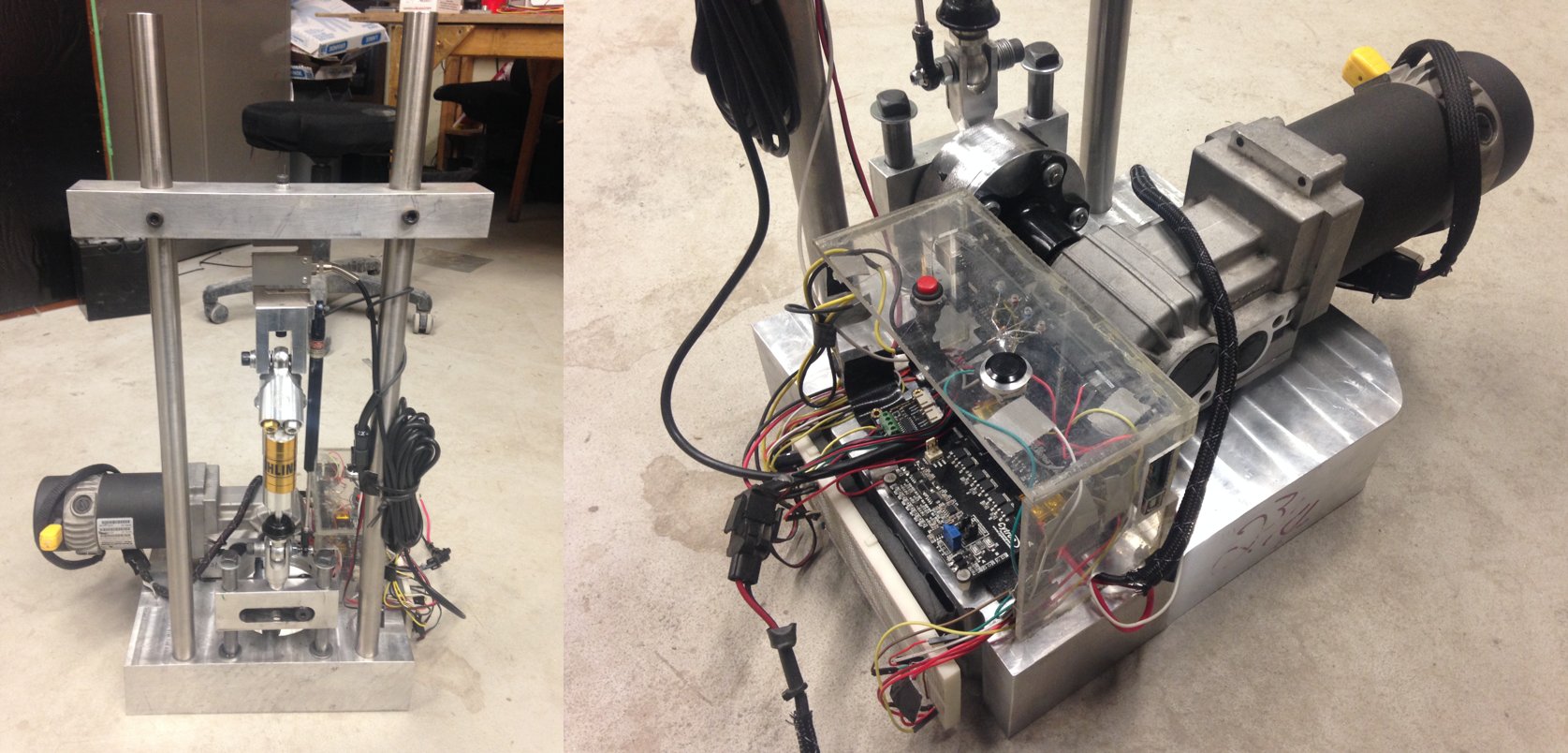
Shock Dynomometer - University Design Project
#mechanical #automotive #electrical #programming #data-analysis #hands-onThis was a past group project. The course requirements for the project were broad; any electromechanical system which uses a relatively simple design and includes an in-depth modeling component. The group decided to build a custom damper dynamometer in cooperation with the Gryphon Racing FSAE team. My focuses included mechanical design, manufacturing, and damper modeling.
Technical Details
This device is used to test damper force versus velocity for different valve adjustments and fluid temperatures. To produce oscillating motion, a large DC motor is connected to a scotch yoke mechanism using a cam follower. The data to be measured during a test is as follows:
• Damper displacement (linear potentiometer)
• Motor RPM (hall effect sensor)
• Damper force (load cell)
• Damper temperature (temp. sensor)
The test results can be used to investigate the operating behavior of the dampers and construct a realistic empirical model. The model being developed is simple but useful; it’s main parameters are:
• RCE : Ratio between compression and extension forces for a given sweep
• CD : Damping coefficient (mean initial slope of compression and extension curves)
• λ: Non-linearity coefficient
By calculating these parameters under varying test conditions, the dampers full range of capabilities can be understood. The intended end result is that a reasonable initial setup can be determined to meet given vehicle performance requirements. Further tuning of the equipment can then be done based on actual on-track vehicle testing.
